What's new
Carbonite

South Africa's Top Online Tech Classifieds!
Register a free account today to become a member! (No Under 18's)
Home of C.U.D.

[Buildlog] DIY 3d printers

Hey @Arphaxad_23 , looking great!\
Where did you purchase those Blind Joint Rails for the frame?

I am following you on this build, very cool.

Not sure what you mean by blind joint rails? 🙈, but bought the linear rails from aliexpress, could not find a local supplier to date.
I would love some pointers to local businesses that I can source component from.

Thank you, I'm glad you enjoy this build-log.
 
Ah ok thanks. I went with the name I saw in the manual...wasnt sure what they were called either ;)

Saying that, I am sure it is still not the actual name, but perhaps just the way the rails connect hahaha

58367
 
Last edited:
Ah ok thanks. I went with the name I saw in the manual...wasnt sure what they were called either ;)

Saying that, I am sure it is still not the actual name, but perhaps just the way the rails connect hahaha

Ahh...now I'm with you. The frame are 20mm x 20mm aluminum profiles, mostly they refer to them as 2020 profiles.
I buy all my profiles from Shop - Modular Assembly SA .They are super cheap, and note you get all sorts of sizes (2040, 3030, 3060...think you get the idea)

As for the blind joint, they are simply referring there to the method of connecting the profiles together. Blind joint is a simple bolt as per the manual.
The other types of joints are utilizing corner cubes like this link

Hope this clears it up for you:D
 
This is one example of why I love 3D printing so much. Simple jigs to cut a bunch of 5mm shafts of various lengths.
Note also one jig has cut-outs to easily grind down flats for the pulley grub screws to have a good flat contact surface.
5TJZvr2.jpg


The stepper motors with dampeners.
pJckH40.jpg


This is what the final four z axis stepper assemblies will look like. Now only three more to go (It's quite fiddly to assemble)
sqh8ka7.jpg
Xm9u8Ij.jpg
jzYk9HR.jpg
 
This is the gantry assembly. You can see the four belts on the corners that will facilitate the z direction movement. The two steppers on this gantry are for the x and y movement with the core xy kinematics. The y linear rails will be mounted to the bottom of both the left and right 'arm'


Some more close ups
lu46Fkw.jpg
JuLkG8J.jpg


Here is a quick fit of the x 'arm' with the hot-end assembly on.The x linear rail will be mounted to the bottom of this arm.
1sj0vMN.jpg


This is the frame, the four corners will get linear rails for smooth z motion. At this stage I'm waiting on all the linear rails to arrive from china. At least I got the first shipment earlier this week!
0DaKgay.jpg


Stay tuned, things are getting real now. I'm super excited :D
 
Last edited:
Good day everybody. May you all have a happy Monday!
So, I made a bit of progress this weekend. Only thing holding me back at this stage is the linear rails.
In the meantime I will start wiring and cable management.
iRt2gEK.jpg


YL9xiip.jpg
ieKYnc5.jpg
S8rYqfT.jpg
1PAjGYe.jpg
63vbrci.jpg


I also took the aluminum plate to a local machine shop to flat the one side with a reasonable tolerance. I trust this will alleviate future bed leveling issues.
gyi4pwC.jpg
 
Been a while since my last update. I was waiting for the linear rails to arrive from china.
Finally got them last week and continued the assembly. Here are the rails:
IYS5AOH.jpg


Rails installed and started with the belts
hBoRl5Z.jpg


Printer flipped on its head to show the two y rails and the one x rail. Everything is moving nice, but not too smooth...hop they don't bind up from misalignment from my side
wDwUmaS.jpg


Here are the sacrificial tape measure that was cut to length. This will be the "back-bone" for the wiring in the braided sleeve.
Elegant solution I think (well the final product). I am not a huge fan of cable chains.
dPEiRVk.jpg
i7e0793.jpg


Next up is starting the wiring. Have some 24 AWG for the signal wires and waiting for the 20 AWG to be delivered for the steppers.
One thing I learned from the clone i3 was that most diy stuff then to break allot (or its just me) and I want to do all the wiring in the machine to be modular.
Thus have one wire harness to all components and then simply plug in each component.

Edit: Anyone know why the linked images in my previous posts are broken?
 
Are you keeping a tab on cost? Would like to know when you are done how much the cost was. Time I guess is also important, but in my case it would be a fun thing to do, so cost would be more important for me.
 
Side note: All images were removed from Carb. Some issue they had.
And that measuring tape use is priceless haha :)
 
Side note: All images were removed from Carb. Some issue they had.
And that measuring tape use is priceless haha :)
Yes, I am aware of this and following that I have replaced all my images with links to imgur. Some now also broken, and tried to replace them...no dice😔
Yeah...I like the tape measure solution (not my idea though)
 
Are you keeping a tab on cost? Would like to know when you are done how much the cost was. Time I guess is also important, but in my case it would be a fun thing to do, so cost would be more important for me.
Not really anymore, gave up a while back😅 (My initial estimate was around R18k)
But, I intend to do a summary once I'm done to get a final cost....I'm a little afraid tbh.

The china stuff was around R12k. This was stuff like the linear rails, steppers, bearings (which I found a cheaper local bearing shop that stocks those odd small bearings) and a bunch of small items I could not source locally at the time.
 
Not much to show, finally got the wiring I ordered.
Some shots showing the process. Added cloth tape to the sides to the measuring tape.
My plan to keep track of all the wires and their purpose is to put small heat shrink on the individual wires on both sides.
Cant see why this wont help!
NGm4zAJ.jpg
n3YAebI.jpg


Here I was done with the x-carriage .... then discovered I used the y-carriage tape which is a different length (yeah you can see the big red "Y" I wrote on the tape 🙈)
Pay attention Arphaxad!. But this will give you a basic idea of how the final wiring harness will look like.
HD5ruTN.jpg
 
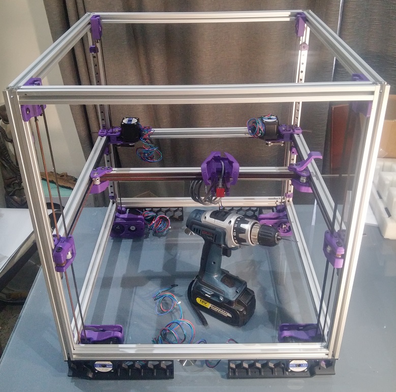
Thought I would share the suppliers of where I sourced the components.

1. Moduasm. For all the Alu profiles, some of the t-slot nuts and bolts.
I would suggest you buy the 2020 profiles slightly (10mm) larger and get a machine shop to mill the ends perfectly 90deg and to correct length.

2.SA Bolt. All the Socket and Button head screws.

3. The following shops I compare prices and buy where the specific items are the cheapest. Stuff like the Ramps 1.4 kits, GT pulleys, psu and random bits
DIY Electronics - They have Capricorn PTFE tube and PEI sheets (not the recommended triangle labs PTFE, but I heard the Capricorn is good quality)
3D Printing Store - Bought the 600W AC heater from them.
Netram - They have 5mm shafts, the FSR (without a board), SN04-N Inductive Proximity sensor and angle 2020 brackets (Not the recommended PL-08N though, but i'll give it a shot....after all the voron does not rely on mesh bed level)
Hobbytronics - 24AWG UL1007 wire and heat shrink assortment packs (Their stepper motors are priced very good and they also have a large variety of linear shafts)
MicroRobotics - They are a bit expensive, but they have 12V-5V usb dc-dc converters (On that, I tried these boards and they seem underpowered ...cant use the WiFi on the pi with them)

4. Da Vinci Lab. Genuine E3D stuff (Not sure about this one, have bought from them but not a hot end as of yet. All my hot ends I imported from E3D)

5. RS Components. I know they are expensive, but I love them. I buy stuff like fans, wiring (20AWG UL1061), molex & DuPont connectors, heat shrink, braided cable sleeves, the funny assortment of tapes the Voron specs, locktite, HEPA filters and diodes.

6. Fena Bearings. Don't bother to google them, its a local bearing shop that actually had stock of the odd sized bearings the spec calls for.

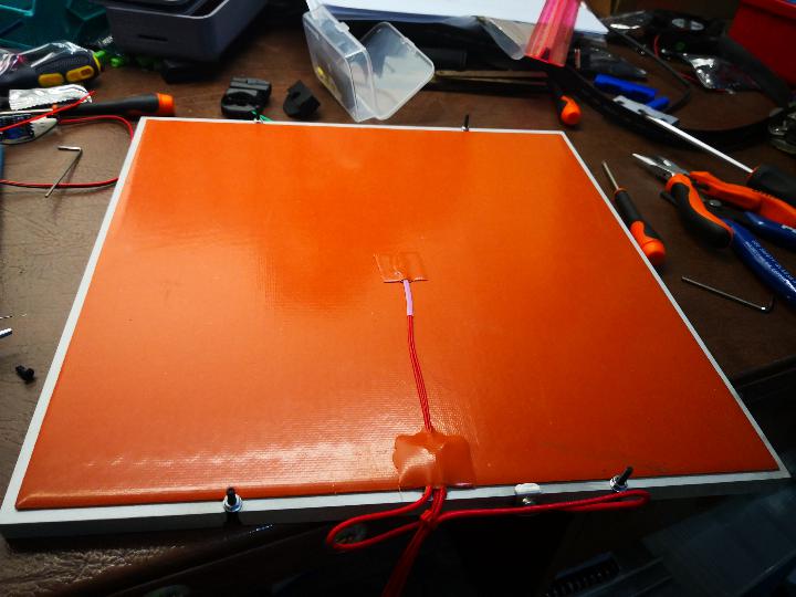
7. Isizwe Metals. Bought the alu bed plates from them, they cut to size. Could not source a casted alu plate locally.

8. Maizey Plastics (alt link). The sides, front & top acrylic panels and the bottom & back coroplast panels.

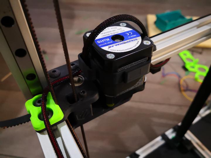
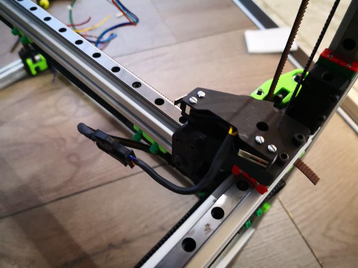
The following I could not source from local suppliers and had to import.
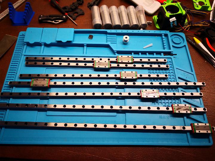
Linear rails, the beefier nema 17 stepper motors (stepperonline) and the better quality 2GT belts (hopefully)

Any other shops anyone recommends?
I know of mantech (hate their search function), communica and 3drone.
 
Met Arphaxad on the Voron forum, good to know there's other South Africans building this guy..

My progress so far (drill for scale) .. still need to assemble the hotend part and then .. electronics 🥶


FFCTvm4.jpg
 
Better be quick, the better half is going to want her dining room table back soon ..
 
The wiring for the Voron is almost done. Only the basement and hot end wiring to be done.
Here are some shots of the cable tape chains and cables managed nicely (or at least I think so!)
The A and B steppers from the bottom. Found those nice clips that holds the molex connectors in place.
k3PL759.jpg
dN8AqxH.jpg


Again the A and B stepper but this time from the top. Notice the clips around the steppers that helps with keeping the wires in place.
7QYJiPb.jpg
SvE6KOe.jpg


The X and Y limit switches. (Added cable clips this morning, so it looks even better that this)
zoqonxo.jpg


Some shots of the cable tape chains on the X and Y arms. The Z you can see in one of the previous pics.
MCP2zHE.jpg
JZrnZIq.jpg
OENFFAG.jpg
 
I also finished mounting the LCD.
JYkZVGN.jpg
3O1MvGg.jpg


Hopefully you can make out the hinge system with the following pics (from bottom perspective).
tP9k0Yq.jpg
Y0nV9qG.jpg


Then finally the basement layout for all the electronics and the hot end mess. Still a fair amount of work to do here. I must say, the closer I get to power this thing on...the scarier it gets.
2LKhUNg.jpg
C1idbcD.jpg
 
Met Arphaxad on the Voron forum, good to know there's other South Africans building this guy..

My progress so far (drill for scale) .. still need to assemble the hotend part and then .. electronics 🥶

Ahh..I like the purple allot! Not the typical you see.

How square did you manage to get your frame?
I'm a bit concerned about mine. The Z plane is about 1mm out of square😬
 
Awesome job you are doing there!
I think as long as you are able to move the print head sub frame without obvious binding in the linear bearings it should be fine. I machined the frame 2020s to size in sets of four and installed the sets in the same orientation, more than that I can't really do. I'm stuck on the hot end assembly at the moment since the heater cartridge I chose is a 50w unit and its thicker wiring does not fit in the slot provided. I have Creality blowers on it and the left unit has the cable coming out towards the front which is also in the way. May have to modify and reprint some parts there.
 
Seeing all of this is awesome and makes me want to try it myself but I'm afraid I know as close to ZERO about the hardware side of things.
So, in lieu of that, when are we seeing prices for getting you guys to print us stuff!!! I have a few items I need.
 
Okay, the hot-end is all wired up!
(Excuse the horrid blurry photo...that happens when you rush 🙈)

9M6IISK.jpg
Dajpc3B.jpg
ti5t1qz.jpg


Finished the assembly of the Mobius 3 extruder as well.

SoMiZoP.jpg
cSh9WGc.jpg


The back extractor fan assembly is also fitted and ready for the fan (This gets a HEPA filter to lean those nasty ABS particles)

D17Us02.jpg
v6PgHLm.jpg


Its starting to look like a finished product. So happy and excited!

fotI4yj.jpg
 
Awesome job you are doing there!
I think as long as you are able to move the print head sub frame without obvious binding in the linear bearings it should be fine. I machined the frame 2020s to size in sets of four and installed the sets in the same orientation, more than that I can't really do. I'm stuck on the hot end assembly at the moment since the heater cartridge I chose is a 50w unit and its thicker wiring does not fit in the slot provided. I have Creality blowers on it and the left unit has the cable coming out towards the front which is also in the way. May have to modify and reprint some parts there.

Thank you very much!
Maybe try the parts that they designed for the E3D volcano ... maybe those have adequate space for beefier wires?
I also have the creality blower fans on..i peeled the crap on the back off and bent the wires a bit back. Seems to fit nicely.
 
Seeing all of this is awesome and makes me want to try it myself but I'm afraid I know as close to ZERO about the hardware side of things.
So, in lieu of that, when are we seeing prices for getting you guys to print us stuff!!! I have a few items I need.

Don't be afraid, you will definitely learn a ton!

The two reasons for building this printer is to get the nice speed boost to spit out parts faster and I think it look more professional when every thing is neat and tidy. Hate showing clients the heavy sloppy diy prusa i3 clone...

But give a shout if you want to print something, there are many of us here on the forum that can help out!
 
Hey @Arphaxad_23 maybe I missed it in the course of your posts and whatnot, but where are you located? I'm sometimes in need of some CNC work and since you're a hobbyist, you might just tick the boxes I'm looking for :D
 
I see a 2.1.1 release was done with updated fan ducts VoronDesign/Voron-2

Ahh...I saw the update post, but obviously I did not read thoroughly.

Hey @Arphaxad_23 maybe I missed it in the course of your posts and whatnot, but where are you located? I'm sometimes in need of some CNC work and since you're a hobbyist, you might just tick the boxes I'm looking for :D

I'm far from most, way up north in a town once called Pietersburg.
At this stage I only have a couple 3d printers in my cnc arsenal, so I unfortunately wont be able to help with cnc routing, cnc milling and laser cutting.
(Maybe I should change hobbyist to enthusiast)
But soon, most parts are ordered for a cnc router.
(So watch out for a build log on that!)
 
Each day is one step closer! Installed the bed heater and the PEI sheet on the alu plate.
310mm x 310mm x 10mm plate (milled down to 9mm to hopefully get a more true surface with a tolerance of about +- 0.03mm)
The heater is a 600W 230V, I actually read after I bought the heater that you don't want to pump more than 0.6W/cm2 into an alu plate otherwise the thermal "shock" will worsen the warping when heating.
Thus at full 600W, I will be pumping 0.62W/cm2 into the plate. No idea how correct this is, any mechanical engineers here that care to shed some light on the subject?
F02uauq.jpg


I also installed a thermal fuse to the side of the plate with a working temp of 133 deg C. Any mitigation of potentially burning down the house is welcome.
My clone i3 actually scares me.
EUgCQ7x.jpg


The other side with the PEI sheet. I'm not too happy about the cable management for the thermal fuse, but it will have to do for now.
x5fD4yD.jpg
BVChaOM.jpg


I started with the wiring in the basement of the printer. All power routed to the respective boards. Tonight its time to connect the steppers and signal wires.
So like I said, getting very close to actually printing. I'm not too concerned about the firmware configuration as I have converted the clone i3 to the pi/klipper setup and is fairly familiar with it.

On a side note, I love 3d printing and it has its advantages (eg. for prototyping), but it's not meant for mass production.
So I completed a mold making course this past weekend (next one scheduled for next month) and intend to combine the two for larger orders of the same item.
 

Users who are viewing this thread

Latest posts

Back
Top Bottom