What's new
Carbonite

South Africa's Top Online Tech Classifieds!
Register a free account today to become a member! (No Under 18's)
Home of C.U.D.

LED lights DIY

Had this been any other usage then just video shooting I would be looking at the below items , cause this is what I will be purchasing soon should be around 500usd landed
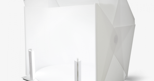
 
I know probably trying to limit wire, but what if you split the wire coming direct from the power into 2?
 

Hi guys,

So above is the set up. All hooked up and going (despite some questionable soldering.)

The LEDS closest to the power line are the brightest and they fade down the circuit. This will probably work for now and we will just save up for proper lightening but for the time being this is perfect.

Thank you to everyone on this thread for your input. If you have a suggestion for upping the brightness further down the line pop me a dm. Otherwise this thread is pretty much done.
Great, the brightness drop down the line is to be expected.
You can improve this by powering the LEDs from both sides, known as Power Injection, effectively mitigating the voltage drop caused by internal resistance of the conductors in the LED strips.

4CEOmL2.png


The image above is for individually addressable LEDs, so yours will need to be connecting all 4 wires on both sides
 
I know probably trying to limit wire, but what if you split the wire coming direct from the power into 2?

This was my initial idea. But with my questionable wiring skills I opted to keep the soldered parts furthest from the carpeted floor as possible.
 
Great, the brightness drop down the line is to be expected.
You can improve this by powering the LEDs from both sides, known as Power Injection, effectively mitigating the voltage drop caused by internal resistance of the conductors in the LED strips.

4CEOmL2.png


The image above is for individually addressable LEDs, so yours will need to be connecting all 4 wires on both sides

I may just get an additional power supply to come from the other end this is a great idea. Problem is this will mess with the colour adjuster as the power will not be sent through the control box but this should not be a huge problem right? If we want to use the control box I will just disconnect the power at the other end.
 
I may just get an additional power supply to come from the other end this is a great idea. Problem is this will mess with the colour adjuster as the power will not be sent through the control box but this should not be a huge problem right? If we want to use the control box I will just disconnect the power at the other end.
You don't need an additional power supply, and yes, that would mess with the colour control unit. Just split the set of four wires coming out of your colour control into two sets - then connect to both ends of your LED loop.

(You'll actually already gain a bunch by only connecting the V+ (usually black wire) on both sides, but looping the three grounds(RGB) as well would be ideal)

It's not about providing more power for the circuit, it's about making the circuit less lossy.

Exactly what this man says.
 

Users who are viewing this thread

Latest posts

Back
Top Bottom