What's new
Carbonite

South Africa's Top Online Tech Classifieds!
Register a free account today to become a member! (No Under 18's)
Home of C.U.D.

CFE Battery help - SOC 97% after 4 days?

eY_b0ss

Official Carbonite Gheylord™
Rating - 100%
180   0   0
Joined
Nov 8, 2014
Messages
2,202
Reaction score
2,632
Points
8,885
Age
34
Location
Murrayfield, Pretoria
Hi guys, I need some help.

Recently installed half a solar system (need the solar panels still, no stock).

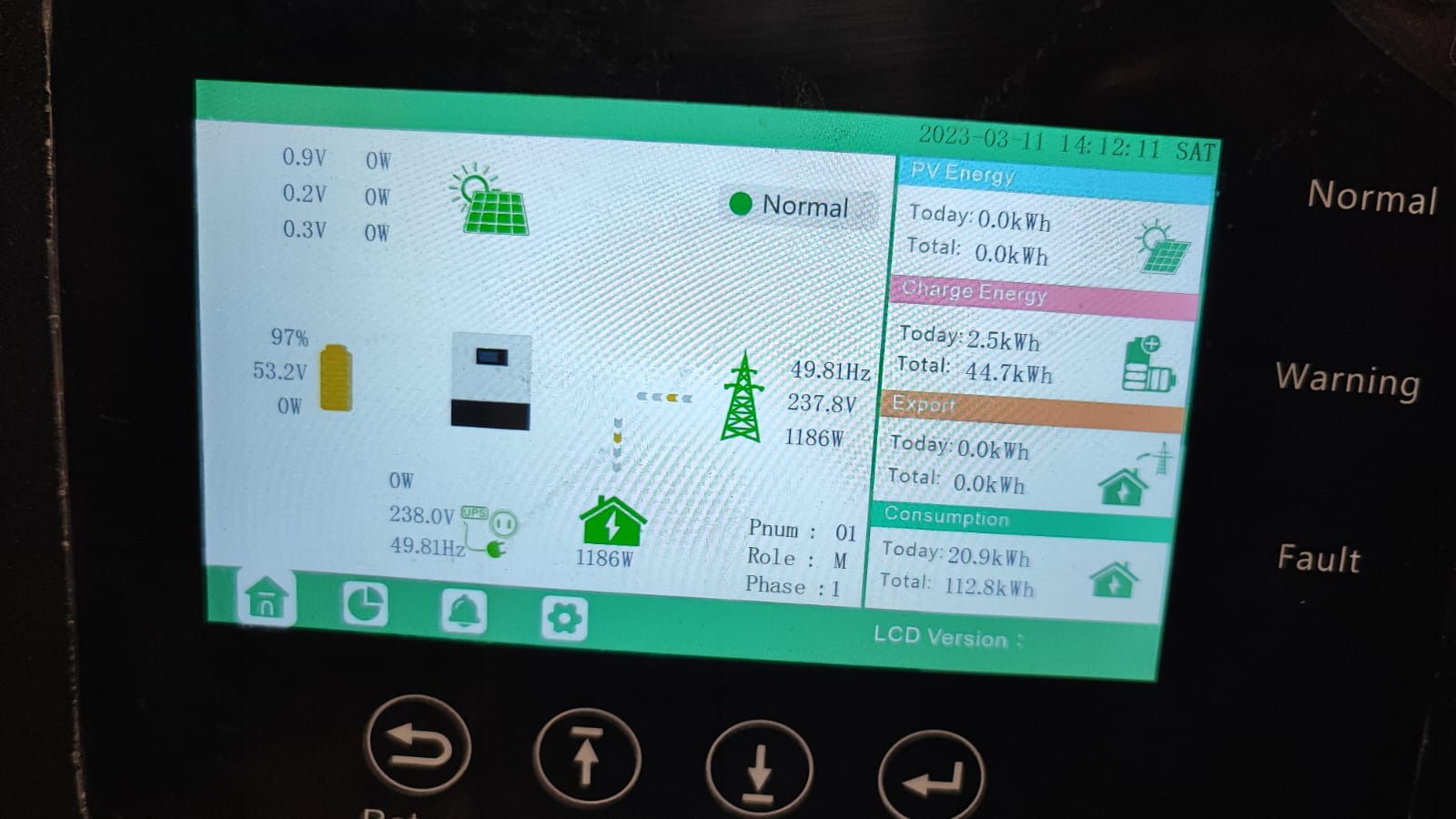
I have a 12kw Luxpower inverter.
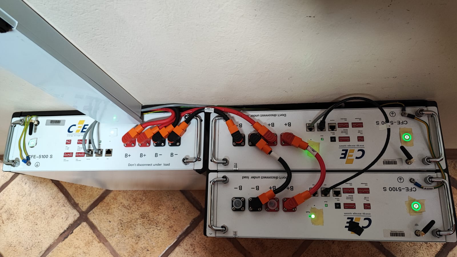
3* 5.12Kwh CFE Batteries.

I've had it for +-4 days now. The battery SOC has fallen from 100% to 97% since then. The installer had them charging from 120A, I have since changed that myself to 60A as stated in battery manual.

The lowest charged they've fallen to since installation was 74%.

Some reason I can't connect to the batteries to monitor them (using wifi), even though they have that ability. The "Smart BESS" app just time's out when you try to connect a battery to it.

I'm afraid my batteries might be losing life, so need to sort this out. PS I am a noob, so any advise would be appreciated.

PS. Powerforum account is waiting validation. You guys are all i have atm xD

28KRYFi.jpg


761wr8l.jpg
 
SOC or SOH?
SOC is state of charge, SOH is state of health.
The BMS inside them will limit the charging current to what the battery can handle. I have my inverter set to charge at 20A and the BMS limits it to 15/16A
So the installer was fine for putting the charge on 120A.
 
That looks like it’s SOC is 97%.

Is the comms between the inverter and battery working or is is reading the SOC based on voltage.

If there’s no bms comms then you would need to set the various charging voltages or sometimes even with the bms comms, this still needs to be set. Float, absorption, equalization. Check the battery manual and check what’s configured on the inverter.

Lastly, let it cycle a bit more.
 
Battery cables connected wrong.
+ and - must not go from one batt to inverter
Umm. The batteries are in parallel. So connected right.

But do note that those cables appear to be quite small. Double check what they are rated for.
If they are rated for 100A, you cannot charge at 125A until you install a second set of cables from the inverter to the batteries (connected to the last battery with the open terminals.)

@eY_b0ss Actually, looking at the pictures again. I am quite concerned. It appears you have a 12kVA inverter. 12000W / 48V = 250A. This means that the wire must be able to handle 250A on discarge. According to SANS 10142-1, the wiring code, for 250A dc inside trunking, you need 120 sq mm copper conductors. There is no way that cable is that size. (SANS 10142-1 Ed 3.1 table 6.2, page 95). Follow up with you electrician immediately. This appears to be a fire risk.

Secondly, nothing wrong with 97% SoC. Typically the SoC is an average-ish of all the cells. But one cell might be slightly higher and so the BMS is telling the charger to back off charging until that particular cell rebalances. It should go back to 100% over time. Give it a couple of hours to rebalance.

Lastly, as stated, SoC (State of Charge) is not SoH (State of Health).
 
Last edited:
Also it appears that those batteries have max discharge of 3kVA.
You have 3 of them. But a 12kVA inverter. You might need to restrict the load by placing an appropriate breaker on the output until you have enough batteries to handle full load.
 
Umm. The batteries are in parallel. So connected right.

But do note that those cables appear to be quite small. Double check what they are rated for.
If they are rated for 100A, you cannot charge at 125A until you install a second set of cables from the inverter to the batteries (connected to the last battery with the open terminals.)

@eY_b0ss Actually, looking at the pictures again. I am quite concerned. It appears you have a 12kVA inverter. 12000W / 48V = 250A. This means that the wire must be able to handle 250A on discarge. According to SANS 10142-1, the wiring code, for 250A dc inside trunking, you need 120 sq mm copper conductors. There is no way that cable is that size. (SANS 10142-1 Ed 3.1 table 6.2, page 95). Follow up with you electrician immediately. This appears to be a fire risk.

Secondly, nothing wrong with 97% SoC. Typically the SoC is an average-ish of all the cells. But one cell might be slightly higher and so the BMS is telling the charger to back off charging until that particular cell rebalances. It should go back to 100% over time. Give it a couple of hours to rebalance.

Lastly, as stated, SoC (State of Charge) is not SoH (State of Health).
Well, it really depends on the fuse that is used between the inverter and battery. If the fuse is appropriately rated, it’s not really a risk.

The fuse / breaker is there to protect the cables.

Those cables look similar to the pylontech cables which are rated at 125A (provided the same quality of insulation is being used). So another set in parallel Is definitely needed in this case unless the power on the inverter is limited to 125A, which is around 6KW.
 
Umm. The batteries are in parallel. So connected right.

But do note that those cables appear to be quite small. Double check what they are rated for.
If they are rated for 100A, you cannot charge at 125A until you install a second set of cables from the inverter to the batteries (connected to the last battery with the open terminals.)

@eY_b0ss Actually, looking at the pictures again. I am quite concerned. It appears you have a 12kVA inverter. 12000W / 48V = 250A. This means that the wire must be able to handle 250A on discarge. According to SANS 10142-1, the wiring code, for 250A dc inside trunking, you need 120 sq mm copper conductors. There is no way that cable is that size. (SANS 10142-1 Ed 3.1 table 6.2, page 95). Follow up with you electrician immediately. This appears to be a fire risk.

Secondly, nothing wrong with 97% SoC. Typically the SoC is an average-ish of all the cells. But one cell might be slightly higher and so the BMS is telling the charger to back off charging until that particular cell rebalances. It should go back to 100% over time. Give it a couple of hours to rebalance.

Lastly, as stated, SoC (State of Charge) is not SoH (State of Health).

Not sure of CFE, but Pylontechs recommend the following as per the manual as @ettiene points out.


Umm. The batteries are in parallel. So connected right.

But do note that those cables appear to be quite small. Double check what they are rated for.
If they are rated for 100A, you cannot charge at 125A until you install a second set of cables from the inverter to the batteries (connected to the last battery with the open terminals.)

@eY_b0ss Actually, looking at the pictures again. I am quite concerned. It appears you have a 12kVA inverter. 12000W / 48V = 250A. This means that the wire must be able to handle 250A on discarge. According to SANS 10142-1, the wiring code, for 250A dc inside trunking, you need 120 sq mm copper conductors. There is no way that cable is that size. (SANS 10142-1 Ed 3.1 table 6.2, page 95). Follow up with you electrician immediately. This appears to be a fire risk.

Secondly, nothing wrong with 97% SoC. Typically the SoC is an average-ish of all the cells. But one cell might be slightly higher and so the BMS is telling the charger to back off charging until that particular cell rebalances. It should go back to 100% over time. Give it a couple of hours to rebalance.

Lastly, as stated, SoC (State of Charge) is not SoH (State of Health).
Please contact Victron then to remove / correct the false information they give in this document. Page 17 specifically.

 
Please contact Victron then to remove / correct the false information they give in this document. Page 17 specifically.

Um, so you are quoting a document on Lead Acid batteries and how to wire them to say that the wiring of the Lithium batteries are incorrect?

Yes, there are certain preferred methods, but that is the whole idea behind the Li-BMS. To balance cells and ensure that they are evenly charged. Lead Acid does not typically have a BMS and you need to ensure even charging by wiring correctly.

No I will not contact Victron. They are perfectly correct for Lead Acid batteries. But we are not talking about that.
 
Ohms law doesn't care what battery chemistry you are using.

The fact remains the way the batteries are currently connected the closest one to inverter will work the hardest during discharge / charge because it has a lower resistance path to and from the inverter, whereas the last one in the chain has a higher resistance because there is more wire lenght between it and the inverter.

Very easy to confirm this, draw a high load from batteries and measure voltage at each ones terminals, they won't match.

A BMS inside a battery is not able to compensate for voltage drop on cables outside the battery. Seems you don't understand exactly what's the function/ purpose of a BMS.
Yes, The battery closest to the inverter might drain faster. But how much?

I did some napkin math.

1/0AWG is 0.116Ohm/1000ft (Source: Google)
Approx 1ft is used per jumper(30CM) (Guesstimate)
Thus 0,000116Ohm per wire (0.116/1000)

Lets assume they are drawing 250A (I don't see any indication that it's a 12KW Inverter but OK)
V=I*R
V=250-0.000116
V=0.029 per jumper.
4*0.029 = 0.116V
One of those jumpers is twice the length of the other.
So lets say we added another 0.029
That's 0.145V
That's basically negligible.

Also the BMS will protect the battery in this situation. The first battery will drain a neglible amount faster, but it WILL cut out when it reaches the low voltage threshold, and the other batteries will get the chance to drain that small amount too.
However if the inverter is set up right this point will never ever be reached.

The terminals is basically a chunk of copper on the inside.
So the first battery cutting out will not affect the others.

And lets not forget this is a theoretical "Under full load for extended time" situation that only exists in my engineering textbooks.
If the inverter and batteries are run at this high of a load for extended periods of time there are many other points that will fail way before the jumpers GIVEN they are specced correctly.

Umm. The batteries are in parallel. So connected right.

But do note that those cables appear to be quite small. Double check what they are rated for.
If they are rated for 100A, you cannot charge at 125A until you install a second set of cables from the inverter to the batteries (connected to the last battery with the open terminals.)

@eY_b0ss Actually, looking at the pictures again. I am quite concerned. It appears you have a 12kVA inverter. 12000W / 48V = 250A. This means that the wire must be able to handle 250A on discarge. According to SANS 10142-1, the wiring code, for 250A dc inside trunking, you need 120 sq mm copper conductors. There is no way that cable is that size. (SANS 10142-1 Ed 3.1 table 6.2, page 95). Follow up with you electrician immediately. This appears to be a fire risk.

Secondly, nothing wrong with 97% SoC. Typically the SoC is an average-ish of all the cells. But one cell might be slightly higher and so the BMS is telling the charger to back off charging until that particular cell rebalances. It should go back to 100% over time. Give it a couple of hours to rebalance.

Lastly, as stated, SoC (State of Charge) is not SoH (State of Health).

I do agree that the jumpers should be double checked.
 
@ettiene No, I fully understand. But you are missing the problem. I believe you are on the first peak of the Dunning–Kruger effect.

The problem is that if you had LE batteries in parallel, some of the batteries will work harder. And since the inverter measures the voltage over the total bank, it might very well be that some batteries are lower in voltage and therefore the inverter will not know when to shut down. Resulting in some batteries getting over discharged leading to premature failure.

The same with when charging the batteries, the cells closer will results in more gassing when charging leading to premature electrolyte loss. Leading to premature failure.

This is not a issue with Lithium batteries. The BMS should take care of a lot of the cell balancing and ensuring that one cell is not overcharged/discharged. Look at the Pylontech manual above for Lithium batteries. They are wired exactly like he has them wired.

Lastly, I have over 20 years engineering and installation experience in renewable RnD. I understand where you are coming from, but with three small Lithium batteries it is not going to make a significant difference. Temperature/rate of charge/discharge/cycle usage/etc with have much bigger impact on the battery life. (If you had a large lead acid battery bank, then sure, uneven current does become a problem.)

However, his house catching fire from using undersized cables is more of an issue. It is my recommendation is that he rather use two cables because of the fire risk, which will solve the hypothetical uneven current draw anyway.

@Adagio_Leopard Geez. You using the American "oght" cable gauge bring back memories of working in the US on an inverter projects. I hated doing everything in Imperial sizes. Please just use metric sizes for maths ;)
1 foot = 12 inches = 25.4mm x 12 = 294mm. Why are you using 300mm? ;)
Oh, OP posted that it is a 12kVA inverter. The link in first post is also for 12kVA inverter.
 
Last edited:
@Adagio_Leopard Geez. You using the American "oght" cable gauge bring back memories of working in the US on an inverter projects. I hated doing everything in Imperial sizes. Please just use metric sizes for maths ;)
1 foot = 12 inches = 25.4mm x 12 = 294mm. Why are you using 300mm? ;)
Oh, OP posted that it is a 12kVA inverter. The link in first post is also for 12kVA inverter.
My sir. In engineering pi is 3 and a foot is 300mm

:ROFLMAO::ROFLMAO::ROFLMAO:

It's friday afternoon and I did not have the want to translate freedom eagles to metric this time.
 

Users who are viewing this thread

Back
Top Bottom