What's new
Carbonite

South Africa's Top Online Tech Classifieds!
Register a free account today to become a member! (No Under 18's)
Home of C.U.D.

What to use to measure line load?

Juggy

Premium Carbonite supporter
VIP Supporter
Rating - 100%
175   0   0
Joined
Apr 22, 2010
Messages
3,402
Reaction score
232
Points
5,615
Age
50
Location
Doha, Qatar
I am looking for a decent device to measure the amount of power my computer draws. Something I can install between the wall and the computer

I have found a few cheapish looking devices but would like something of decent quality. I saw a device they used on Linus Tech Tips which looked good but I couldn't make out what it was exactly

UK plug is preferred.
 
A clamp multimeter is the right tool if it’s for a temporary/once off measurement.

For a longer term solution the only way is CUD ;)
Get an i-series Corsair PSU and you can monitor from software.

I have some smart plugs that report power draw in real-time and long term logging. I think most smart plugs have that feature.

I’m sure there’s a cheaper solution out there though.

A multimeter is a great idea and is a tool I can use in the future as well however I do need a permanent type solution so will go with an inline plug.

I was looking at the HX1000i but stocks seem to be limited at the moment.
 
A clamp multimeter is the right tool if it’s for a temporary/once off measurement.

For a longer term solution the only way is CUD ;)
Get an i-series Corsair PSU and you can monitor from software.

I have some smart plugs that report power draw in real-time and long term logging. I think most smart plugs have that feature.

I’m sure there’s a cheaper solution out there though.
A clamp multimeter is the wrong tool. You cannot measure voltage accurately, and also not power factor. You also have to clamp only one of the wires otherwise the magnetic fields cancel out, so you have to destroy a lead or make a custom cable.

The kill-a-watt type is probably the easiest solution.
 
A clamp multimeter is the right tool if it’s for a temporary/once off measurement.

For a longer term solution the only way is CUD ;)
Get an i-series Corsair PSU and you can monitor from software.

I have some smart plugs that report power draw in real-time and long term logging. I think most smart plugs have that feature.

I’m sure there’s a cheaper solution out there though.
Came here to say this... clamp meter with self made cable. Measure the draw (max expected load) and stash it away. Quick simple and cheap and you'll use your meter for a thousand other things in future. Best "bang for buck" option if you ask me, many of these smart plugs cost the same as a decent multi meter and can only be used for 1 thing.
 
A clamp multimeter is the wrong tool. You cannot measure voltage accurately, and also not power factor. You also have to clamp only one of the wires otherwise the magnetic fields cancel out, so you have to destroy a lead or make a custom cable.

The kill-a-watt type is probably the easiest solution.

Voltage is known(ish) - you just need to measure current and you're sorted.
You're right about having to measure one wire though - forgot about that.

I was looking at the HX1000i but stocks seem to be limited at the moment.

Surely an RMi would do the job? Not sure which models run on USB and which need a Commander.
Also, 1000W seems excessive. An RM850i would be plenty and I believe it uses USB.
 
Killawatt's good for this,measure multiple stats like peak,total,current comsumption
 
Voltage is known(ish) - you just need to measure current and you're sorted.
You're right about having to measure one wire though - forgot about that.


Surely an RMi would do the job? Not sure which models run on USB and which need a Commander.
Also, 1000W seems excessive. An RM850i would be plenty and I believe it uses USB.
Well, if does power factor correction, then sure, otherwise you will be out by quite a margin...

The RMxxxi power supplies are complete rubbish when it comes to measuring power. Mine would report 50W when it was using 100W etc. As far as I can tell, it fudges the numbers on purpose so that the efficiency looks good. On the secondary low voltage side, current is only reported to the nearest 1A, which is not very useful. I have looked at the topology and design of the supply, it is based off a reference design. They definitely measure more accurately internally...
 
Voltage is known(ish) - you just need to measure current and you're sorted.
You're right about having to measure one wire though - forgot about that.

If your Volts fluctuate more than 10% (+/- 2.3V) you have bigger issues than worrying about monitoring your current draw tbh and you'll need to clean up your supply via an inverter. So being able to measure "accurate" Voltage is a fairly moot point (if you are already on clean power, measuring accurate voltage IS a moot point) - SA in general is on 230V supply with fluctuations around 10% from what I've heard (I am not a expert so don't hold me to this). The overall impact this Volt fluctuation will have a small impact on your overall draw calculation (Watts = Volts * Amps. On a theoretical 5AMP current, the wattage variation will be around 12 Watts which is quite small in a normal household environment).

But I get it, CUD is CUD. I'm just saying a multi-meter is a lekker tool/toy to have, and can do a lot more than a kill-a-watt.


Surely an RMi would do the job? Not sure which models run on USB and which need a Commander.
Also, 1000W seems excessive. An RM850i would be plenty and I believe it uses USB.
 
For a quick solution, just get a Kill-A-Watt. They rarely drop in price, but it is a bit overpriced for what it is. Only downside is that it only displays instantaneous measurements, and a lumped sum recorded since the last reset.
If, however, you have the time to try out something really cool, you can get a current sensor and arduino with a wifi card for around R400 in total, and then use that to record measurements to a frequency of your choice, and then setup a mqtt, and flask docker container on your computer. Mqtt is a machine-to-machine communication protocol used for DIY smart homes, and flask will allow you to host a local python based webserver which can capture, store, and display this data to you in real time. From that you can get valuable long term information, regressions, etc. And more importantly, you'll learn a lot during the process.

You have me intrigued, what exactly do I need and how would a wifi enabled device record power usage?
 
You have me intrigued, what exactly do I need and how would a wifi enabled device record power usage?
The wifi chip is only used to communicate with the Mqtt broker (the server is refereed to as a broker). There are other ways to visualize the data (for example, just using an LCD screen), but transmitting it to a central server for processing, and analysis is just more convenient from a users point of view. You can use any microcontroller, or even a raspberry pi / odroid. As long as it has analog pins, or a way to read analog signals (with an external ADC perhaps).
A current sensor can then be directly connected to the analog input as shown. The data can then be transmitted to the broker as show using this code. The flask server can consist of this code to receive data, and store it in SQLite. If this is a new territory for you, as it was for me, my suggestion is to first setup your software so that devices can easily be added to it, and then purchase your hardware, and implement you code on that.

  1. Get MQTT Server Running
    1. Setup Broker
    2. Setup Client
    3. Setup functions that execute commands on payload received
  2. Setup Database Table
    1. Learn how to setup sqlite tables
    2. Learn how to insert, and select data from database.
    3. Integrate data insertion with mqtt payload received function.
  3. Configure Web server. I have absolutely no formal experience with web development, so this tutorial series helped me a lot
    1. Configure data visualization. For me, high charts worked well for large amounts of data
    2. Configure data visualization updates. (Seems the same as the first, but it is its own challenge)
  4. Now you should have a web server that displays data sent to it in real time. Now you can setup the client which is the device that will be recording and sending the data.
    1. Purchase micro controller and sensors from online stores or Carb
    2. Wait eagerly, as every engineer in South Africa is doing the same, because projects must continue :D
  5. Wire up your circuit
  6. Run your code
  7. Test
    1. Now its not safe to test using 240V AC, so to first ensure that your software and code is working correctly, connect the current sensor to a battery circuit, or if you have, a signal generator.
      1. Data recorded should be shown on the web interface.
  8. If all works well, cross your fingers, plug it in the wall, and hope nothing blows up
Tedious process to some, I must admit. But what you learn from this is more useful, from a tinkerers point of view, than what I've learnt in my entire engineering degree so far. And this system can also be easily configured to send commands from the web interface, allowing you to control items in your house, and record multiple devices on the same web interface.
 
if you really want to do some proper circuit monitor, and are good with DIY

There is a system called open energy monitor. this is very much overkill for just checking a single PC load. but shows many many stats and can do logs, build a nice Grafana dashboard and off you go.

Also... if you run home assistant, you can tie it in nicely for a whole home energy monitoring system.... and it looks fancy when you show your friends

Edit: I love this sort of stuff and have made so many cool projects.
 
The wifi chip is only used to communicate with the Mqtt broker (the server is refereed to as a broker). There are other ways to visualize the data (for example, just using an LCD screen), but transmitting it to a central server for processing, and analysis is just more convenient from a users point of view. You can use any microcontroller, or even a raspberry pi / odroid. As long as it has analog pins, or a way to read analog signals (with an external ADC perhaps).
A current sensor can then be directly connected to the analog input as shown. The data can then be transmitted to the broker as show using this code. The flask server can consist of this code to receive data, and store it in SQLite. If this is a new territory for you, as it was for me, my suggestion is to first setup your software so that devices can easily be added to it, and then purchase your hardware, and implement you code on that.

  1. Get MQTT Server Running
    1. Setup Broker
    2. Setup Client
    3. Setup functions that execute commands on payload received
  2. Setup Database Table
    1. Learn how to setup sqlite tables
    2. Learn how to insert, and select data from database.
    3. Integrate data insertion with mqtt payload received function.
  3. Configure Web server. I have absolutely no formal experience with web development, so this tutorial series helped me a lot
    1. Configure data visualization. For me, high charts worked well for large amounts of data
    2. Configure data visualization updates. (Seems the same as the first, but it is its own challenge)
  4. Now you should have a web server that displays data sent to it in real time. Now you can setup the client which is the device that will be recording and sending the data.
    1. Purchase micro controller and sensors from online stores or Carb
    2. Wait eagerly, as every engineer in South Africa is doing the same, because projects must continue :D
  5. Wire up your circuit
  6. Run your code
  7. Test
    1. Now its not safe to test using 240V AC, so to first ensure that your software and code is working correctly, connect the current sensor to a battery circuit, or if you have, a signal generator.
      1. Data recorded should be shown on the web interface.
  8. If all works well, cross your fingers, plug it in the wall, and hope nothing blows up
Tedious process to some, I must admit. But what you learn from this is more useful, from a tinkerers point of view, than what I've learnt in my entire engineering degree so far. And this system can also be easily configured to send commands from the web interface, allowing you to control items in your house, and record multiple devices on the same web interface.

Damn, that sounds like a lot to do. Unfortunately I do not have the time so will have to settle for something easier.

Thanks for the information though, very interesting.
 
I think my ideal solution would be a multiplug with 5 or 6 sockets on it and individual monitoring on each

Or something similar
 
I eventually found something suitable, wasn't exactly what I wanted but landed up being better.

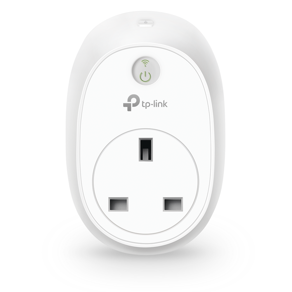
TP-Link Kasa plugs with power monitoring. Hooks up nicely to my Google Home devices, can monitor computer power usage and I can set power on times for my espresso machine


Users who are viewing this thread

Latest posts

Back
Top Bottom